8.1 BASIC DESIGN CONFIGURATIONS OF PROPELLANT TANKS
The configuration of propellant tanks depends largely on vehicle mission and size. In most modern designs, the tanks form an integral part of the vehicle structure. Propellant tanks can be categorized, according to vehicle application, as follows: (1) Prepackaged storable liquid systems (2) Booster stage systems (3) Upper stage systems
Propellant Tanks for Prepackaged Storable Liquid Systems
Figure 8-1 presents the configuration of a typical prepackaged storable liquid propulsion system. The tanks are arranged in tandem, with a common bulkhead between. This system is designed for long storage periods, perhaps 5 to 10 years. A main characteristic of these systems is that the propellants are factory loaded and are hermetically sealed in the tanks by burst diaphragms. Both tank and diaphragm construction materials must be compatible with the propellants for the storage duration. In the example, the propellants are expelled by pressurized gases produced by a solid propellant gas generator. The tank walls form an integral part of the vehicle structure and are designed to withstand the internal pressure loads as well as the vehicle dynamic loads. In some designs the tanks are further stabilized by the internal pressure against buckling; i.e., the walls are always kept under tension loads by a specified pressure level maintained during storage and handling. In smaller units, the walls are usually capable of taking external loads without being pressurized internally. Operational tank pressures for these range from 400 to 2000 psia .
Prepackaged storable liquid systems are usually employed to relatively short-duration, lowthrust applications. Since the tanks form an integral part of the propulsion system, they are designed and furnished by the engine builder. In one design, the thrust chamber is located inside the aft tank and welded directly to the tank bulkhead.
Propellant Tanks for Booster Stage Systems
Figure S-2 presents the propellant tank design configuration of a typical propulsion system as used in the booster stages of a large launch vehicle such as the Saturn V. The system shown can be used for either storable or cryogenic propellants. The tanks are arranged in tandem; their walls form an integral part of the vehicle structure. For booster application, overall vehicle systems optimization usually dictates use of a turbopump-fed engine system. This permits relatively low operational tank pressures, ranging from 30 to 100 psia .
Since the tanks represent a large percentage of the vehicle structural (inert) weight, advantage is taken of the low-pressure levels by constructing the tanks with extremely thin-wall thicknesses. However, the often huge tank structures thus become sensitive to external buckling loads. To stabilize the tank structures of large booster stage systems, two basic design avenues are open: pressure-stabilization and self-supporting structures. In the pressurestabilized systems, such as the Atlas ICBM, the
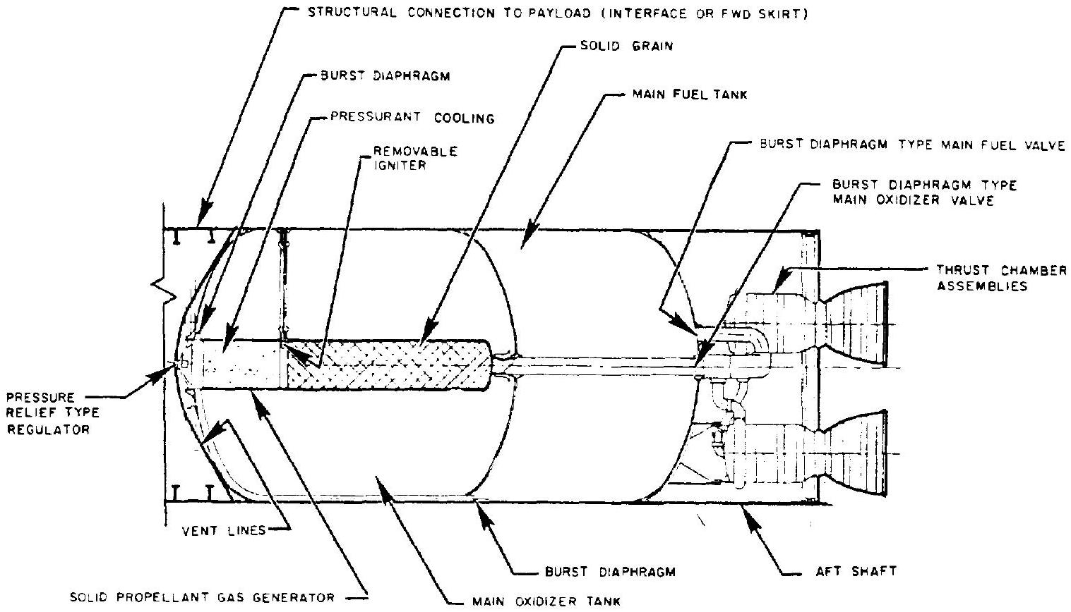 Figure 8-1.-Propellant tank design configuration of a typical prepackaged storable liquid propulsion system.
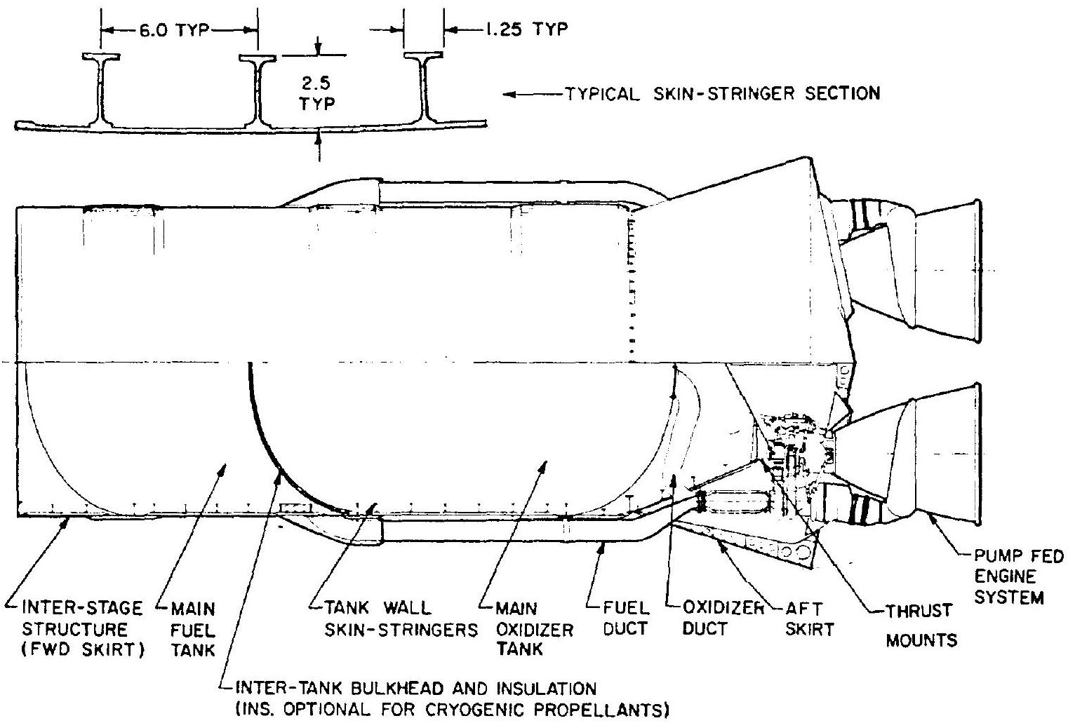 Figure 8-2.-Propellant tank design configuration of a typical booster stage propulsion system.
tank pressures must be constantly maintained above a specified minimum by elaborate controls. This tank structure basically is a thinwall monocoque, requiring special handling procedures. In most booster-stage systems, the propellant tanks are self-supporting types, the tank walls being reinforced by skin stringers (fig. 8-2), or by other structural means, such as waffle grid patterns.
When cryogenic propellants are used, tank insulation may be required. Insulation is mandatory in liquid hydrogen system to prevent ambient air liquefaction which causes high heat transfer rates with attendant high boiloff rates, and safety hazards.
Propellant Tanks for Upper Stage Systems
Figure 8-3 presents the propellant tank design configuration of a typical pressure-fed, upper stage propulsion system. Here, the tanks are contained within an outer cylindrical shell, through which thrust is transmitted to the payload. The shell is designed to withstand all anticipated boost and flight loads. The propellant tankage consists of two individual units. The main fuel tank is located forward, and the main oxidizer tank near the aft end. The two welded aluminum-alloy tanks are modified spheres, faired into conical sections at the bottom, for propellant discharge. The tanks are bolted to the shell structure around their support ring. The thrust chamber assembly is located just below, and closely coupled to, the oxidizer tank. Thrust is transmitted to the outer shell through the aft half of the oxidizer tank. Both tanks may be insulated independently, for cryogenic propellant service.
Many upper-stage vehicles employ a pressurized gas feed propulsion system. Tank pressures range from 100 to 400 psia . The system shown in figure 8-3 uses stored helium gas for
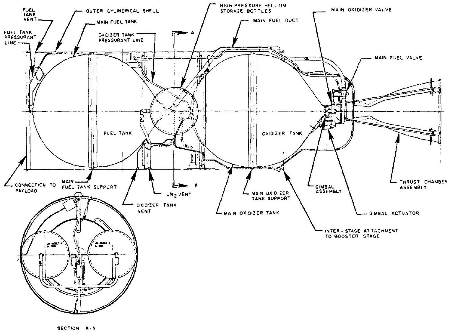 Figure 8-3.-Propellant tank design configuration of a typical upper stage propulsion system.
pressurization. The gas is stored at an initial pressure level from 4500 to 5500 psia at in two liquid-nitrogen-jacketed, high-pressure spherical bottles located between the two main propellant tanks.
It is for upper stage propulsion systems that the engine designer may most likely also design the tankage. The following discussions, therefore, will confine themselves to these systems. By contrast, the design of booster tanks will probably always be made by an independent group. However, many of the design principles presented here are equally applicable to booster tanks and may thus further the understanding of their design problems.